The assignment was to design a 3D printed object that incorporated bearings in a meaningful way and also indicated wind speed and direction.
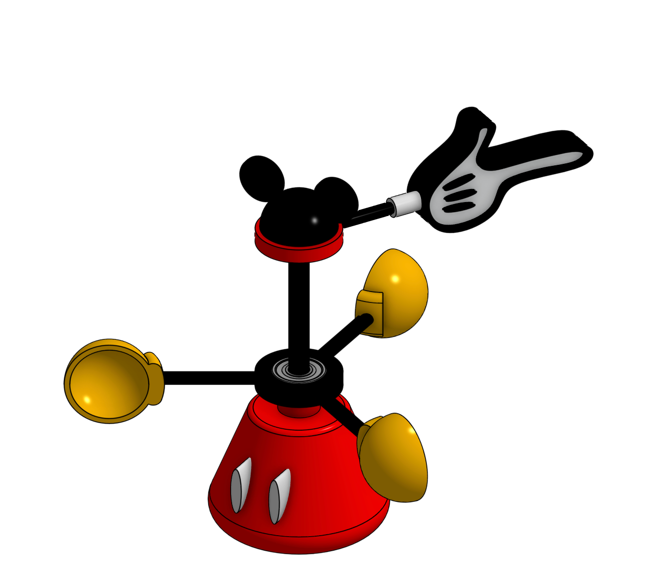
This is the final CAD model
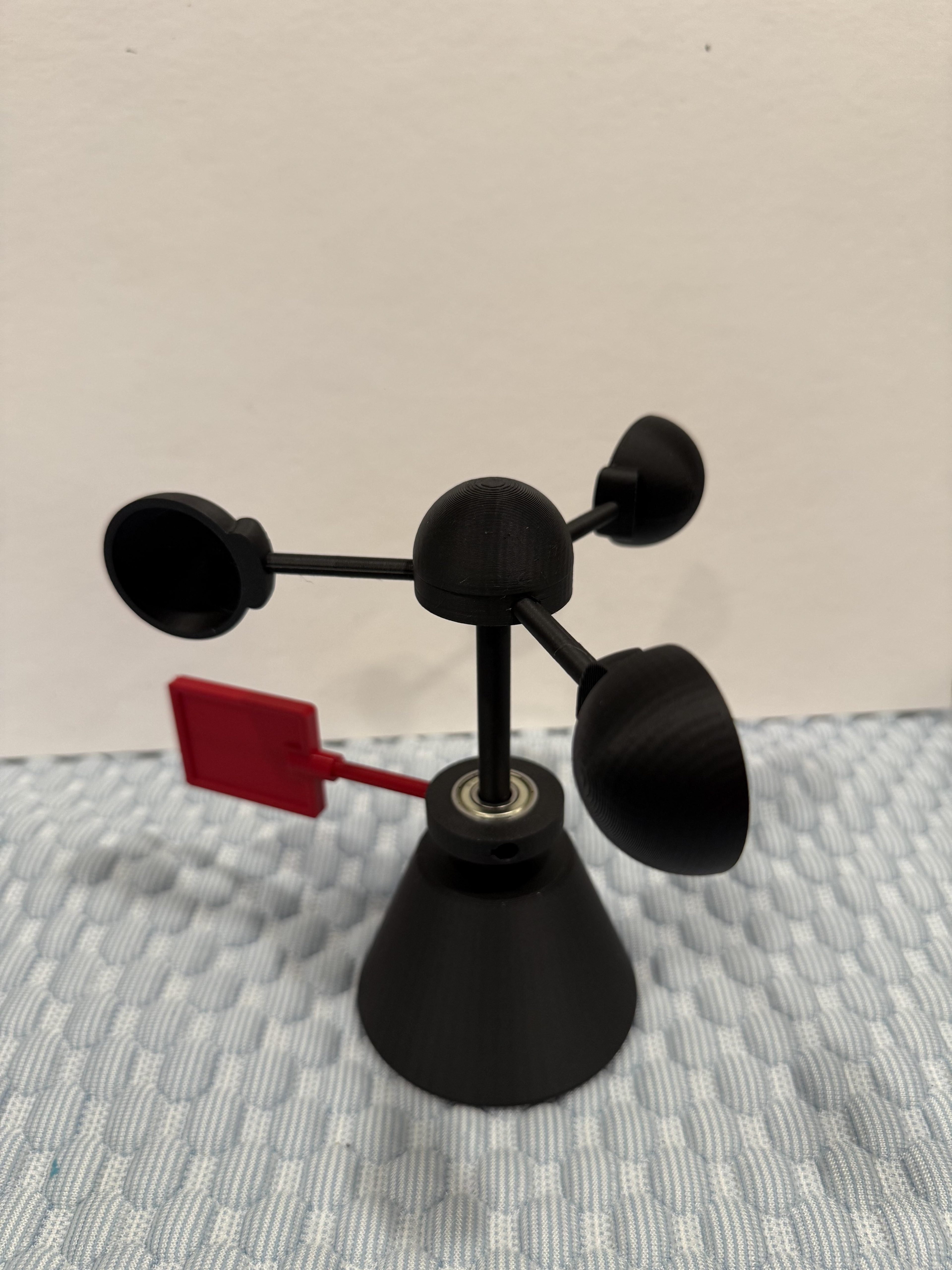
This was the first prototype. I printed it to test tolerances and check functionality of the cup/vane design. It worked! There was a little too much clearance between the shaft and the bearing holes, and the cap on top of the vane scraped the top of the shaft a bit, putting a little too much resistance on the vane. The cups spun well though, and the vane did indicate direction if the wind was strong enough.
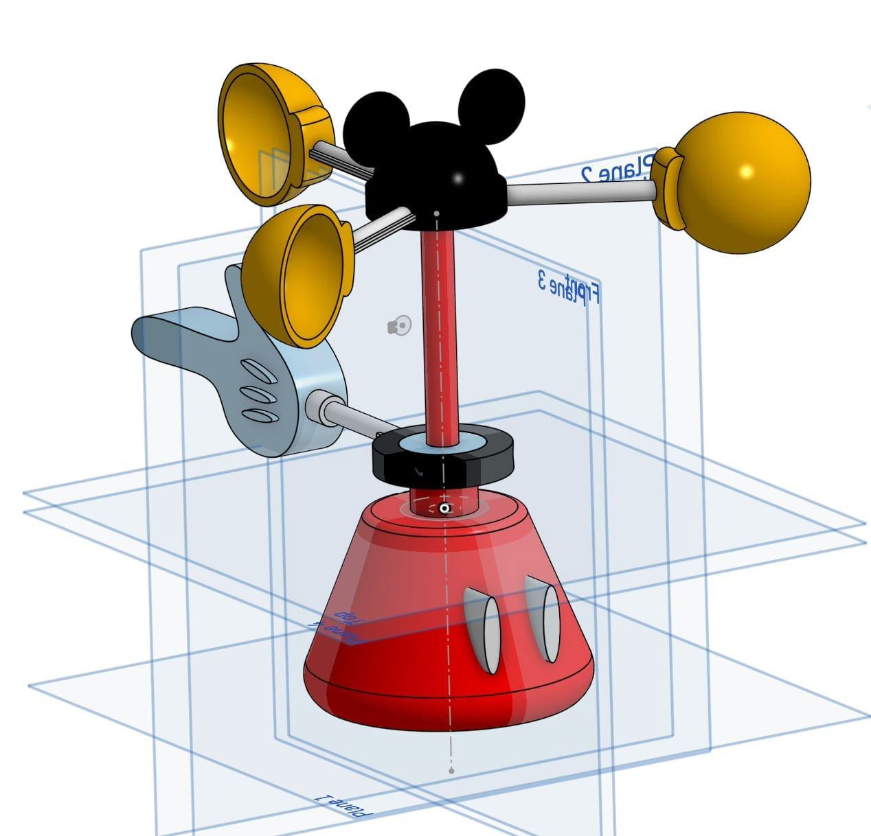
When adjusting the clearances, I also decided to add some theming elements to the anemometer to make it more fun and whimsical. I changed the shapes of the vane, the cap and the base, and added colors. I also hollowed out most of the cap, shortened it and added rounded internal ribs in order to reduce scraping at the top in hopes of making the cups spin a little smoother. It didn't work, though.
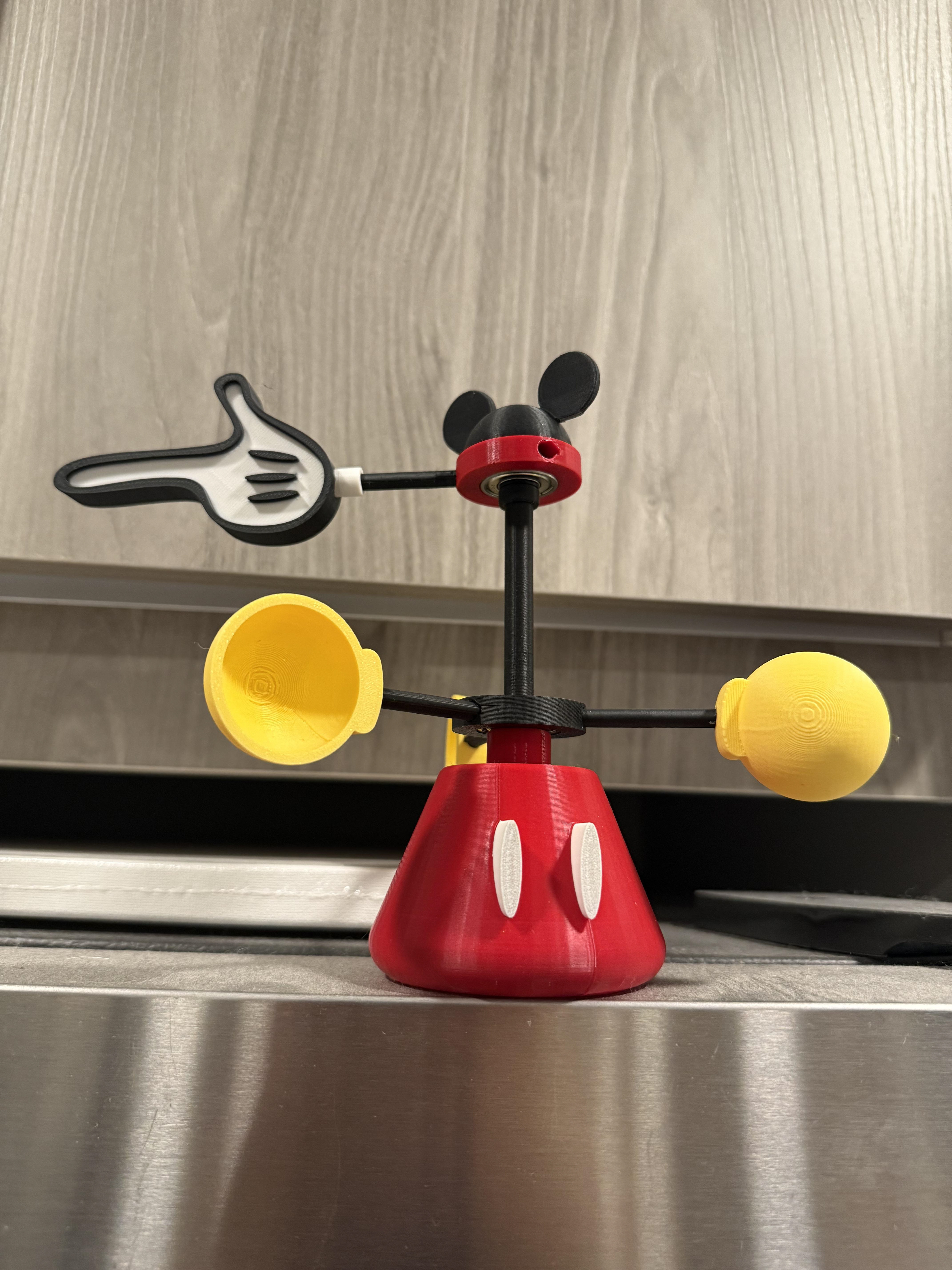
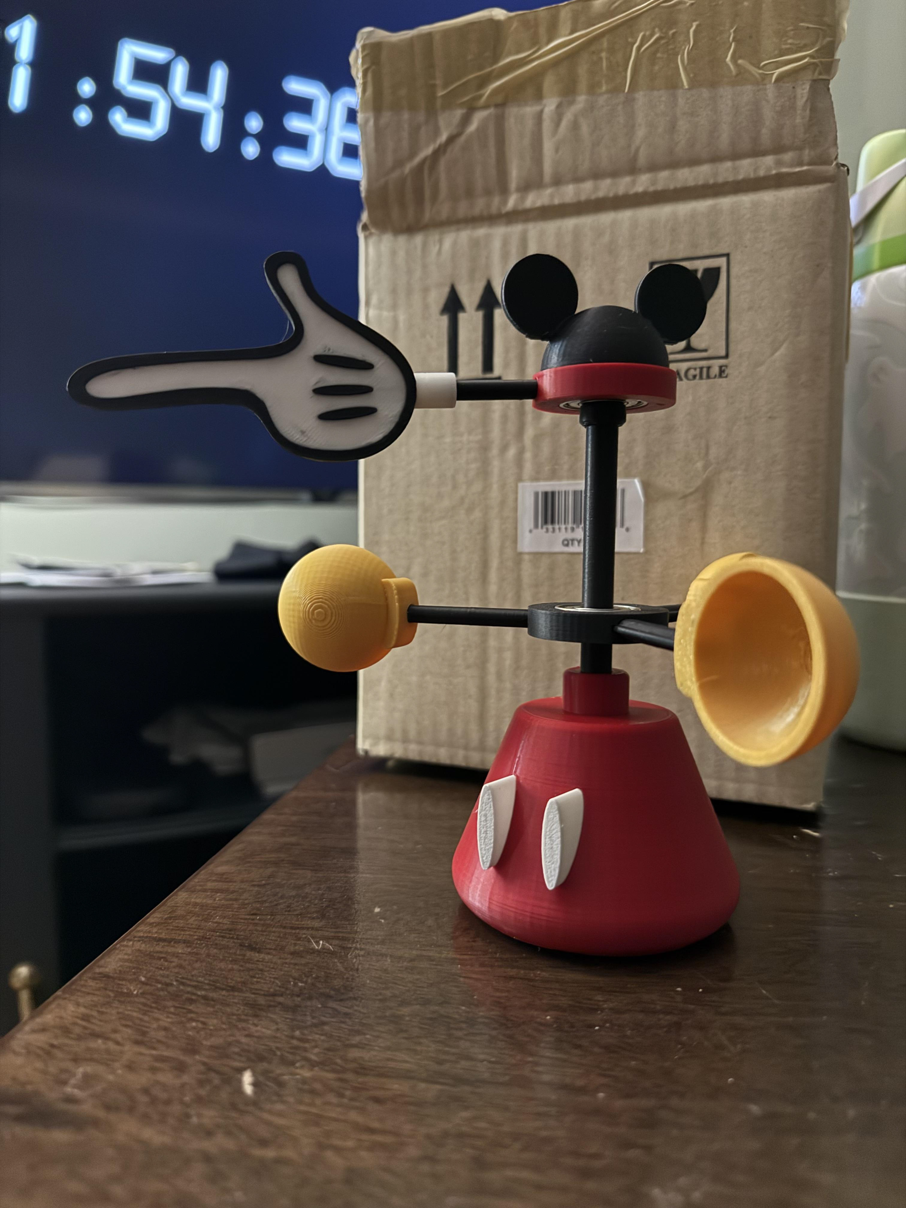
For the next iteration, I swapped the vane and cups to better match the theme. I also thickened the ears at the top so they wouldn't break easily, and created a debossed/embossed effect on the face of the vane to add more depth to the design. The vane spun much better at the top, without the weight of the three cups and shafts pushing it down on the shaft top, but there was still a little resistance. Professor Brown recommended that I add another mass on the opposite side of the ring to balance out the ring.
I also decided to add more weight/infill to the base to avoid it flying off in stronger winds.